Samsung OpenSSL Cryptographic Module
FIPS 140-2 Security Policy
© 2013 Samsung/atsec information security. This document can be reproduced and distributed only whole and intact,
including this copyright notice.
7 of 24
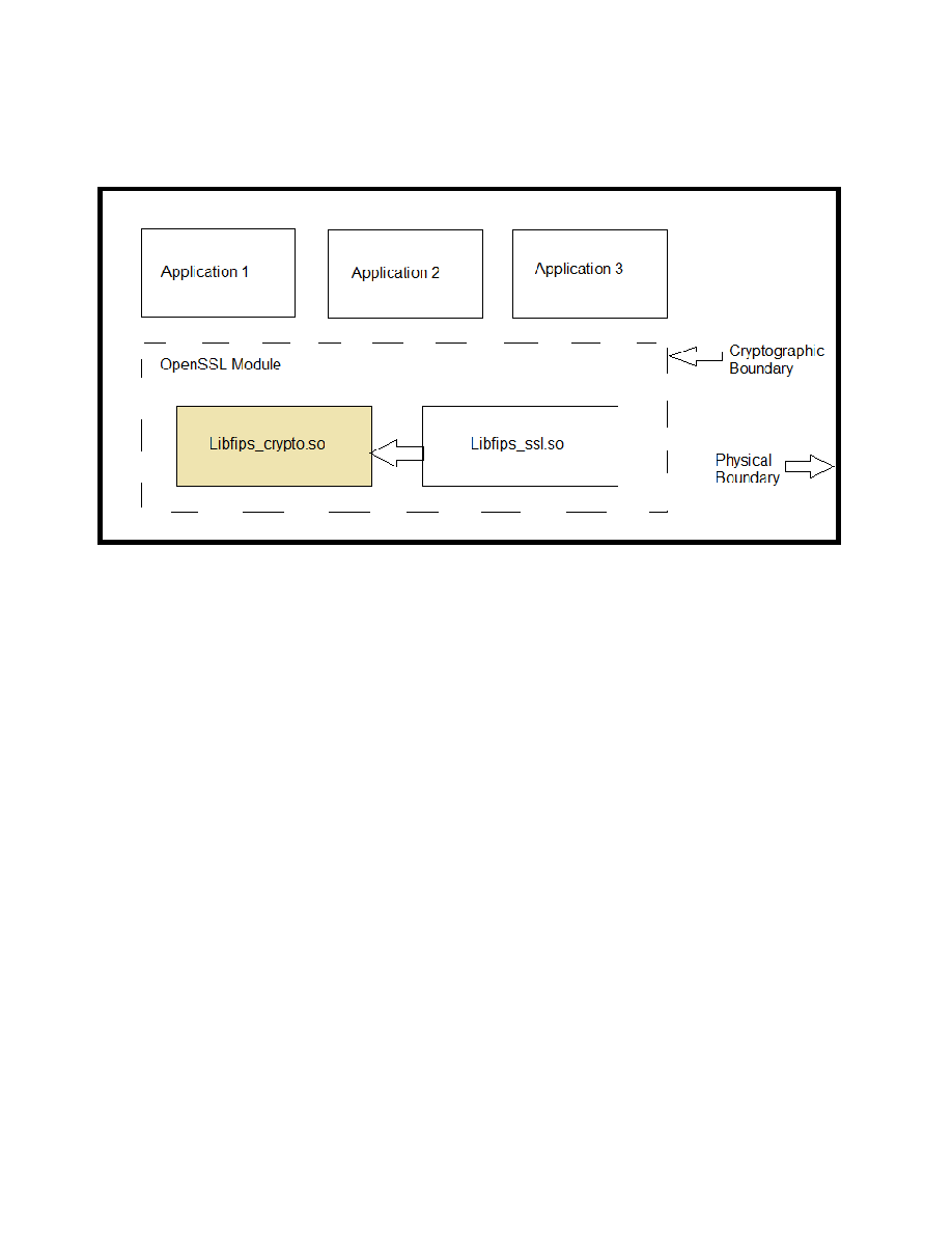
2.3. Cryptographic Module Boundary
2.3.1.Software Block Diagram
Figure 1: Software Block Diagram
Related documentation:
S/W Detailed Level Design (FIPS_OpenSSL_Func_Design.docx) v.13
Samsung OpenSSL Cryptographic Module (Samsung_OpenSSLv1.4.doc)
Note: The master component list is provided in Section 6.3 of S/W Detailed Level Design
document.
2.3.2.Hardware Block Diagram
This figure illustrates the various data, status and control paths through the cryptographic module.
Inside, the physical boundary of the module, the mobile device consists of standard integrated
circuits, including processors and memory. These do not include any security-relevant, semi- or
custom integrated circuits or other active electronic circuit elements. The physical boundary
includes power inputs and outputs, and internal power supplies. The logical boundary of the
cryptographic module contains only the security-relevant software elements that comprise the
module.