Cryptographic Module Ports and Interfaces
FortiGate-200A/200A-HD/300A/300A-HD/500A/500A-HD/800 FIPS 140-2 Security Policy
01-00000-0382-20061201
9
Cryptographic Module Ports and Interfaces
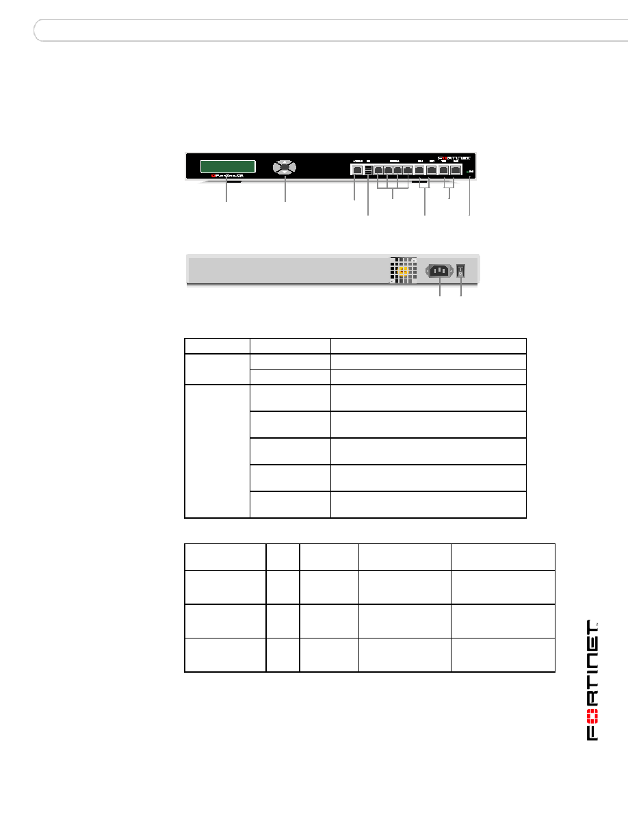
FortiGate-200A and 200A-HD Modules
Figure 1: FortiGate-200A and 200A-HD Front and Rear Panels
Table 2:
LED
State
Description
Power
Green
The FortiGate unit is powered on.
Off
The FortiGate unit is powered off.
All Network
Ports
Amber
(Left LED)
The correct cable is in use and the connected
equipment has power on ports.
Flashing Amber
(Left LED)
Network activity at this interface.
Green
(Right LED)
Ports 1, 2, 3, 4, the interface is connected at
100 Mbps.
Amber
(Right LED)
Ports 5 and 6, the interface is connected at
1000 Mbps.
Off
No link established. (Left LED)
Connection is at 10Mbps. (Right LED)
Table 3: FortiGate-200A and 200A-HD Connectors and Ports
Connector
Type
Speed
Supported Logical
Interfaces
Description
Internal
RJ-45
10/100
Base_T
Data input, data
output, control input
and status output
Default connection to
the internal network. 4
port switched interface.
DMZ1 and 2
RJ-45
10/100
Base_T
Data input, data
output, control input
and status output
Optional connections to
one or two DMZ
networks.
WAN1 and 2
RJ-45
10/100
Base_T
Data input, data
output, control input
and status output
Redundant connections
to the Internet.
Esc
Enter
123
4
Fron t
LCD
Control
Button s
Interna l
(4-port switc h)
Power
LED
DMZ
1, 2
WA N
1, 2
Back
Powe r
Conn ection
Power
Switch
USB
Ports
Console
Port

